Back to Homework...
Postscript Version
Fall 1997 Dr. Havlicek
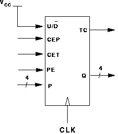
Consider the 4-bit binary up/down counter shown below and notice that
the U/ ![]() input has been tied to TRUE, so that the
counter always counts UP:
input has been tied to TRUE, so that the
counter always counts UP:

Use two such counters to design an 8-bit multistage up counter. Give a schematic diagram of the multistage counter.
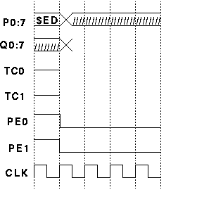
Call the parallel load inputs to the multistage counter P0 through P7. Call the outputs of the multistage counter Q0 through Q7.
Complete the timing diagram shown below. In the timing diagram, append a zero (0) to signal names for the low-order 4-bit counter. Similarly, append a one (1) to signal names for the high-order 4-bit counter in the timing diagram. Thus, in the timing diagram, TC0 indicates the terminal count signal for the low-order counter while TC1 indicates the terminal count signal for the high-order counter.

